First I draw my circuit with pen and paper.

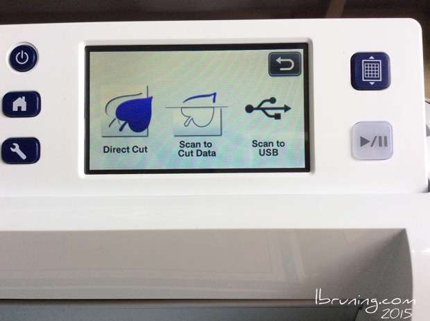
Scan it into the Brother ScanNCut using Scan to Cut Data.
Leave it in place on the cutting mat.
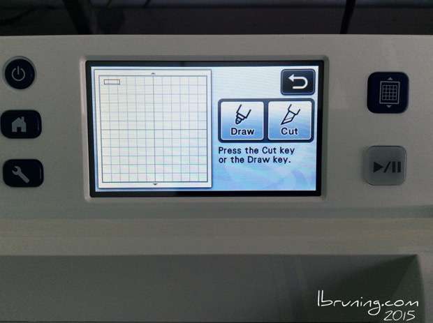
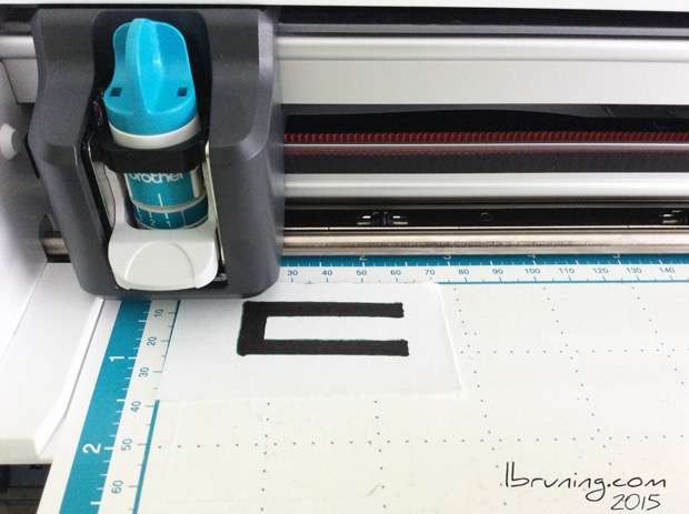
Using the ScanNCut pen attachment draw the circuit on the same piece of paper and check for accuracy against your original image.
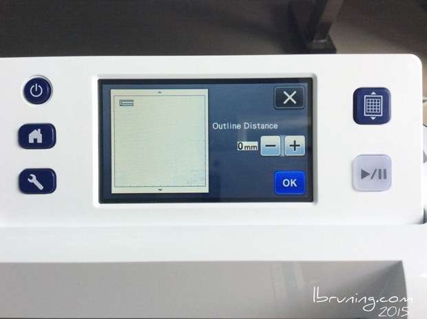
I set the menu to an outline distance pf zero so the pen will just trace along the outline of your original drawing.
If it looks correct SAVE the image to either the machine memory or a USB.
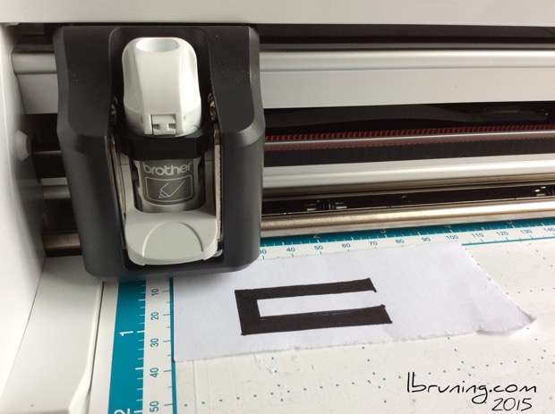
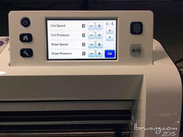
Then cut the saved image on a scrap of paper using a blade setting of 1.
In the settings menu I decrease the pressure to 0.
Remove the sample paper ‘circuit’.
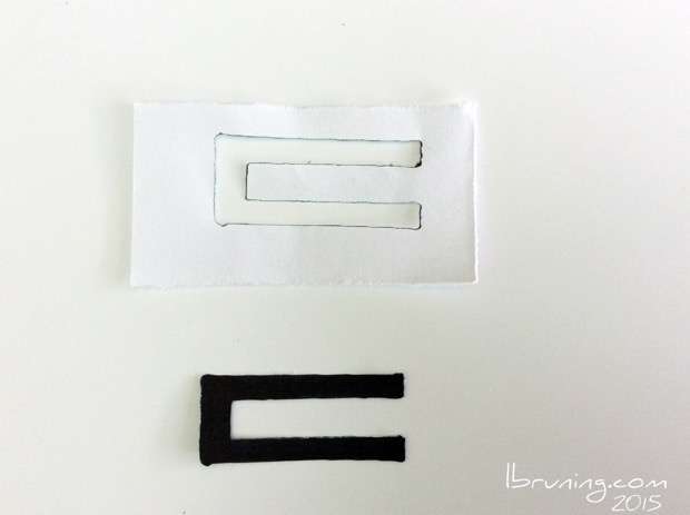
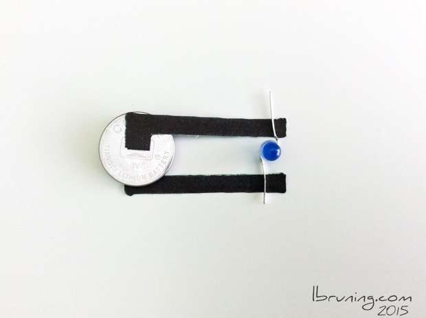
Make any alterations with a scissor. In my example I cut the trace in half so I will have mirror images of a positive and a negative trace.
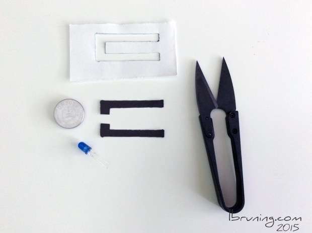
Test it with your hardware and make any adjustments to your circuit template.
Check it one more time…..
and……
…….THEN
…. place the conductive fabric on the mat and cut the circuit image.
Recent Posts
 eTextile Breadboards0
Looking back at the development of my eTextile Reprogramming an ATtiny450
I had finished sewing an Atmel ATtiny45 into a Photosensor Circuit0
These three eTextile circuits use the same Push the Blue Switch!0
Switch circuit breadboard prototype. Conductive Thread from Syscom0
These are threads from Syscom that I have used
Hardware
 4cm x 6cm PCB from eBay seller czb67219600
eBay storefront czb6721960 product photos for Universal Printed Circuit Boards from eBay0
eBay makes my life so simple! Heart Sensors0
Medical Heart Sensor Pads Vector Prototype Boards0
Sorting Harry’s boxes and I unearthed Programming ATtiny45s for PIF0
Traveling is never dull as a I wake at dawn to Speaker Circuit from a Mini Travel Speaker0
I purchased a mini travel speaker from Amazon ATtiny 45 Broken and Exposed0
Supplies
- Conductive Thread from Syscom0
These are threads from Syscom that I have used - 4cm x 6cm PCB from eBay seller czb67219600
eBay storefront czb6721960 product photos for  Universal Pen Holder with Brother ScanNCut20
Brother solved my problem! At PIF Camp we- Universal Printed Circuit Boards from eBay0
eBay makes my life so simple!  Making Circuit Samples with the Brother CutNScan0
First I draw my circuit with pen and paper. NFC Tags0
Near Feild Communication Tags from LENFC. Workbench at Ljudmila – Preparing for PIF0
Testing Metal Clad Thread from Syscom with my
LEDs
- eTextile Breadboards0
Looking back at the development of my eTextile - Reprogramming an ATtiny450
I had finished sewing an Atmel ATtiny45 into a - Photosensor Circuit0
These three eTextile circuits use the same - Push the Blue Switch!0
Switch circuit breadboard prototype. - Conductive Thread from Syscom0
These are threads from Syscom that I have used - 4cm x 6cm PCB from eBay seller czb67219600
eBay storefront czb6721960 product photos for - Universal Pen Holder with Brother ScanNCut20
Brother solved my problem! At PIF Camp we