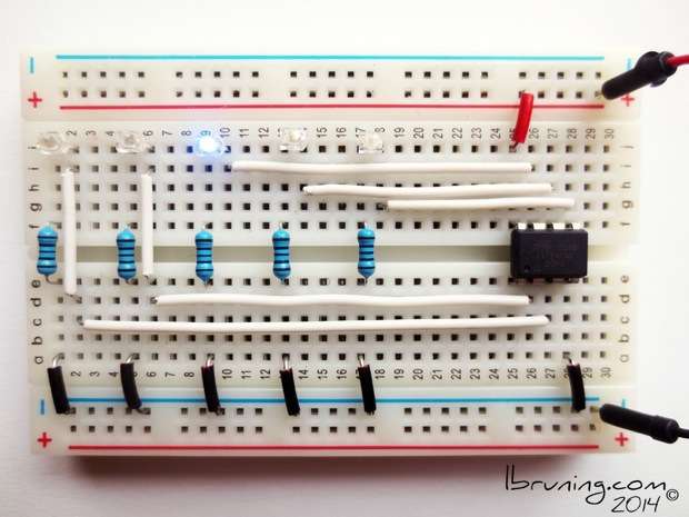
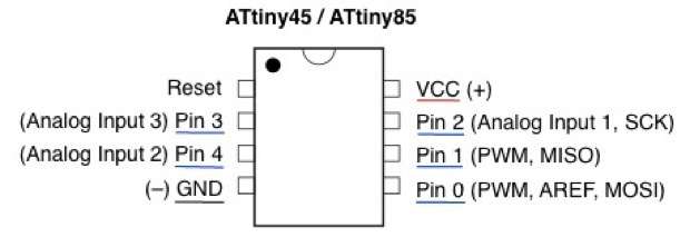
How to set up a breadboard circuit for ATtiny45 to blink five LEDs in sequence.

BREADBOARD CONNECTIONS
ATtiny Pin 0 to LED positive (signal, white)
ATtiny VCC (+) to power positive (+, red)
ATtiny GND (-) to power negative (-, black)
LED negative to resistor (breadboard connection)
Resistor to negative power (-, black)
repeat for Pin 1, Pin 2, Pin 3, and Pin 4

CODE
Upload the following code to an ATtiny45 by following my tutorial on How to Use Ardunio ISP to Program ATtiny45
/*Five LED blink in Sequence Fast with ATtiny45*/
/*9 January 2014*/
/*lynne bruning*/
/*denver*/
int led1 = 0;
int led2 = 1;
int led3 = 2;
int led4 = 3;
int led5 = 4;
// the setup routine runs once when you press reset:
void setup()
// initialize the digital pin as an output.
{
pinMode(led1, OUTPUT);
pinMode(led2, OUTPUT);
pinMode(led3, OUTPUT);
pinMode(led4, OUTPUT);
pinMode(led5, OUTPUT);
}
// the loop routine runs over and over again forever:
void loop()
{
digitalWrite(led1, HIGH); // turn the LED on (HIGH is the voltage level)
delay(100); // wait for a second
digitalWrite(led1, LOW); // turn the LED off (LOW is the voltage level)
delay(100); // wait for a second
digitalWrite(led2, HIGH);
delay(100);
digitalWrite(led2, LOW);
delay(100);
digitalWrite(led3, HIGH);
delay(100);
digitalWrite(led3, LOW);
delay(100);
digitalWrite(led4, HIGH);
delay(100);
digitalWrite(led4, LOW);
delay(100);
digitalWrite(led5, HIGH);
delay(100);
digitalWrite(led5, LOW);
delay(100);
}


