How to set up a breadboard circuit for ATtiny45 to blink one LED.
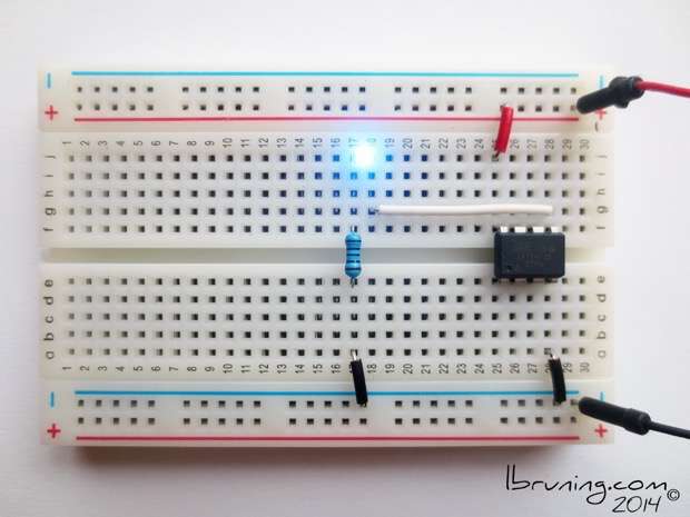
BREADBOARD CONNECTIONS
Connect Power to ATtiny
Power positive to ATtiny VCC (+, red)
Power negative to ATtiny GND (-, black)
Connect LED
LED positive to ATtiny Pin 0 (signal, white)
LED negative to resistor
Resistor to negative power (-, black)
CODE
Upload the following code to an ATtiny45 by following my tutorial on How to Use Ardunio ISP to Program ATtiny45
The following public domain code will a blink one light emitting diode and can also be found in the tool bar under FILE > EXAMPLES > BASIC > BLINK
When using the example code remember to change line 6, Pin 13 to Pin 0.
Or copy/paste the below code into your Arduino Sketch:
/*
Blink
Turns on an LED on for one second, then off for one second, repeatedly.
This example code is in the public domain.
*/
// Pin 0 has an LED connected on most Arduino boards.
// give it a name:
int led = 0;
// the setup routine runs once when you press reset:
void setup() {
// initialize the digital pin as an output.
pinMode(led, OUTPUT);
}
// the loop routine runs over and over again forever:
void loop() {
digitalWrite(led, HIGH); // turn the LED on (HIGH is the voltage level)
delay(1000); // wait for a second
digitalWrite(led, LOW); // turn the LED off by making the voltage LOW
delay(1000); // wait for a second
}
To change the blink speed input a new value for (1000) in the following lines of code:
digitalWrite(led, HIGH); // turn the LED on (HIGH is the voltage level)
delay(1000); // wait for a second
digitalWrite(led, LOW); // turn the LED off by making the voltage LOW
delay(1000); // wait for a second
Enjoy the Blink and Bling!


